LoRaWAN Project
we studied the delay for downlink communications. We focus on Class B of LoRaWAN because Class B is optimized for energy-efficient downlink communications. First, we analyze in details the Class B specification, and we highlight some limitations. Then, we propose an analytic model based on a Markov chain for downlink communications with retransmissions, and we compute the expected delay of these communications under a variety of parameters.
Discussion on limitations of Class B
Duty-cycle limitation for the gateway
We believe that there are issues in Class B in the current version of the standard (version 1.0). We discuss these issues in the following.
- Duty-cycle limitation for the gateway: It is not possible for the gateway to send ACKs for a large number of confirmed uplinks. The gateway cannot acknowledge more than one frame every 66.3 seconds for each sub-band (for DR0 and with an ACK payload of 3 bytes). The gateway cannot acknowledge frames for three or more end-devices per sub-band, with saturated end-devices and a duty-cycle of 1% (for DR0 and for a payload of 30 bytes). It is not possible for the gateway to use most ping slots of Class B. Indeed, each time the gateway sends a small data frame with 10 bytes of payload on a ping slot, it has to wait for 98.13 seconds (with DR0) before using the next ping slot (for all slots using this sub-band). Thus, the number of ping slots N impacts the delay for the first downlink communication, but has a limited impact on the downlink throughput.
- Conflicts between Class A and Class B: The standard does not forbid an end-device to transmit during the beacon transmission of the gateway (as Class A end-devices are not aware of the timing of the beacons) or during the ping slots.
- Delay before ACKs and sub-band availability: The standard does not specify the delay between a confirmed downlink frame from the gateway and the ACK from the end-device (unlike the random backoff during the transmission of a confirmed uplink frame and the reception of the ACK from the gateway, as the ACK is supposed to be received during RX1 or RX2). Moreover, the standard does not specify the delay between the retransmissions of the same frame.
In practice, we can consider that the gateway is able to estimate the sub-band availability of each end-device, by tracking all frames sent by each end-device. When the gateway receives a data frame, it can compute the time-off duration for the end-device, based on the data-rate and on the frame length. When a data frame is not received by the gateway, the gateway assumes that the sub-band is available for the end-device: in this case, the gateway under-estimates the sub-band availability. However, it is not possible for the gateway to over-estimate the sub-band availability: it is not possible for an end-device to send a frame while the gateway assumes that the sub-band is unavailable.
We considered that the ACK transmission from an end-device occurs as soon as possible (that is, immediately after the sub-band becomes available). After waiting for one symbol, if no transmission is detected, the gateway initiates the retransmission procedure: it retransmits the data frame during either the next ping slot or the next receive window.
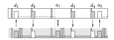
The figure below shows an example of several transmissions. First, an end-device sends a frame d1 which is received by the gateway. Then, the gateway sends a frame d2 during a ping slot. The gateway knows that it cannot receive the ACK until the beginning of the third ping period and initiates the timeout accordingly. When the timeout expires, which is depicted by the dotted line, the gateway expects to receive the ACK. However, a1 is dropped. Then, the gateway resends the frame d3 at the beginning of the next ping slot. The end-device is unable to send another ACK, and has to wait. In the meanwhile, the gateway keeps retransmitting the frame (see frame d4 ), due to the under-estimation of the sub-band availability. Finally, the end-device sends the ACK a2 during the last ping period. It is important to notice that during the timeout (which occurred during the whole second ping period),it is not possible for the end-device to send a data-frame, as all sub-bands were busy. Thus, the gateway either retransmits the frame at the ping slot that follows the timeout (which was the case for frame d3 on this example), or it is possible that the end-device sends a data frame between the end of the timeout and the beginning of the next ping slot.
The standard also mentions that RX2 uses a predefinedchannel. If RX2 is shared by all end-devices and is used by the gateway for one end-device, it cannot be used again until the sub-band becomes available. Note that RX2 is generally used by the gateway when the transmitting end-device chose for RX1 a sub-band which was not available for the gateway.
We assumed that RX2 can be used whenever needed. In other words, we assume that either it uses a sub-band with a large duty-cycle, or that it is on a different sub-band for each end-device.
Analytic model
We make the three following hypotheses.
- There is no queuing delay: the gateway has a single frame to send.
- Uplink and downlink communications do not interfere with each other (due to the use of an opposite chirp).
- We ignore the capture effect: if two end-devices transmit simultaneously on the same channel, both frames are dropped.
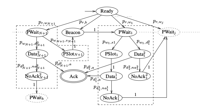
The figure below shows our Markov chain model for confirmed downlink communications in Class B of LoRaWAN. The Ready state corresponds to the generation of a frame by the gateway. The Beacon state represents the beacon reserved period. The PSloti state (for i ∈ [1;N]) represents the i-th ping slot, while PSlotN+1 represents a virtual ping slot where no transmission is possible (it is used only for the delay computation). The PWait1 state represents the random duration between the beacon and the first ping slot. The PWaiti state, for i ∈ [2;N], represents the ping period between the (i−1)-th ping slot and the i-th ping slot. The PWaitN+1 state represents the (random) duration between the N-th ping slot and the beacon. The Data1i (for i ∈ [1;N]) represents the transmission of data during the i-th ping slot (that is, Class B transmission). The Data2i (for i ∈ [1;N+1]) represents the transmission of data during the i-th ping period (that is, during the receive window of a Class A transmission). The ACK state, which is final, represents the reception of an ACK from the end-device. The NoAckji state indicates that no ACK was received after state Dataji , and that a retransmission will occur.
The Ready state is the initial state of our Markov chain. Then, the chain goes to the Beacon state, if the frame was generated during the beacon reserved period, or to a PWait state, if the frame was generated during a ping period. If the frame is generated during the beacon reserved period, the chain goes to the PWait1 state. Let us now focus on this first ping period, represented by the dashed rectangle in the middle of the figure, as it is similar to all other periods (except the (N+1)-th period). Two cases can occur: either the gateway waits for the ping slot to occur, which corresponds to PSlot1 , or a Class A transmission occurs during this ping period, which corresponds to the Data21 state. After PSlot1 , the data is sent in the Data11 state and is either acknowledged (Ack state) or not (NoAck11 state). After Data21 , the data is either acknowledged (Ack state) or not. When there is no ACK, the chain goes to a PWaitj state, possibly several ping periods later, depending on the retransmission delay. Let us now focus on the (N+1)-th ping period, represented by the dashed rectangle on the left: there is no ping slot, so the PSlotN+1 state goes directly to the beacon reserved period (without Data1N+1 state).
Performance evaluation
We evaluate the performance of the class B LoRaWAN for the confirmed downlink frames in terms of the expected delay.
Parameter settings
We focused on the EU863-870MHz ISM band regional settings of the standard. ETSI regulations for the ISM band specify the following four sub-bands (for a bandwidth of 125kHz): sub-band G with 15 channels and 1% duty-cycle, sub-band G1 with 3 channels and 1% duty-cycle, sub-band G2 with 2 channels 0.1% duty-cycle, sub-band G3 with 1 channel and 10% duty-cycle, and sub-band G4 with 1 channel and 1% duty-cycle. In the following, we assumed that all sub-bands have a duty-cycle of 1%. We varied the number of sub-bands n sb from 1 to 3, and the number of channels per sub-band n c from 1 to 3. Given the fact that the gateway has no energy limitation and that its confirmed frames are likely to be important, we assumed that there is no limitation of the number of retransmissions. The link quality is set to α=0.99.
Delay as a function of the data-rate
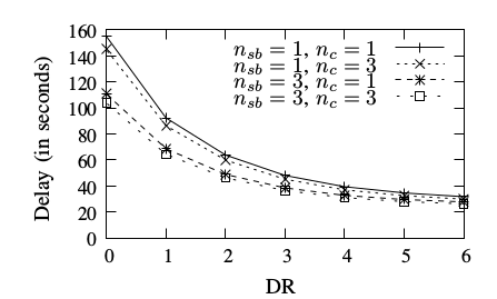
The figure below shows the delay of confirmed downlink frames as a function of the data-rate, for N = 2 ping periods. We assumed here that there are n A = 10 competing nodes. The data-rate has a large impact on the delay, as expected, since increasing the data-rate reduces the time on air of frames, and thus the time-off duration. The number of sub-bands nsb also has a significant impact: the larger nsb , the smaller the delay, as there are more opportunities to transmit a frame. Increasing the number of channels has a limited impact on the delay, however.
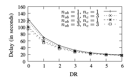
The figure below shows the delay of confirmed downlink frames as a function of the data-rate, for N = 4 ping periods. The data-rate has a large impact on the delay. However, both nsb and nc have a limited impact. By comparison with the figure above, where N=2, it can be seen that increasing the number of ping periods from N = 2 to N = 4 significantly reduced the delay.
Delay as a function of other nodes
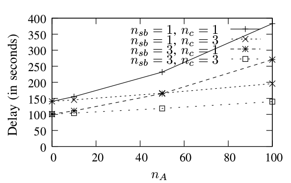
The figure below shows the delay of confirmed downlink frames as a function of the number of competing nodes, for N = 2 ping periods. We assumed here that the data-rate is DR0. The number of competing nodes greatly impacts the delay, especially when the number of channels is low. Indeed, all competing nodes are likely to send frames on the same channel, which results into collisions and retransmissions. Increasing the number of sub-bands from 1 to 3 results into a delay reduction which varies between 25% and 30%.
The figure below shows the delay of confir;end downlink frames as a function of the number of competing nodes, for N = 4 ping periods. Again, increasing the number of sub-bands from 1 to 3 results into a delay reduction which varies between 18% and 22%. By comparison with the figure above, it can be shown that increasing N significantly reduces the delay.
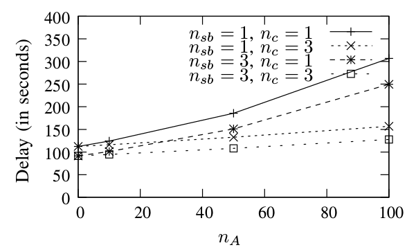
In practive, the choice of N is a trade-off between the energy consumption of end-devices (as they have to wake up shorlty at each ping period) and the delay of downlink frames. It is likely that in many Class B scenarios, N will be larger than 4, which guarantees that a downlink frame can be sent in less then 32s. Thus, according to the results, we expect nsb and nc to have a limited impact on the delay of Class B downlink frames, while the data-rate and nA have a significant impact on the delay.